JieLi (JL) Forced Upgrade Tool 4.0 Upgrade and Download Instructions
1. Upgrade and Download Instructions
Connect the chip’s USB port to a standard USB interface. The first pin is the chip’s power supply pin.
1.1. Upgrade Operations
In most cases, when downloading a program to a development board or prototype, the regular upgrade method is used. In a few cases, certain chips require serial port upgrade (for example, AD15,KT6368A, KT148A, and etc.).
1.1.1. Regular Upgrade
1. DIP Switch Settings for the Forced Upgrade Tool
Use the DIP switch settings shown in the table below to enter upgrade mode:
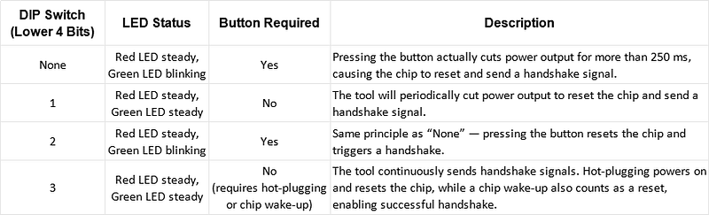
Note: Only one DIP switch bit can be set at a time, and the Forced Upgrade Tool must be reconnected to the PC after each change.
2. Connecting the Chip and the Forced Upgrade Tool
- The USB female port of the tool connects to the PC.
- The USB male port connects to the prototype or development board.
⚠️ Be careful not to reverse the connections (refer to the diagram).

3. Performing the Upgrade Download
After Step 2:
- For “None” or “2” DIP settings → press the button until the green LED turns off and the red LED stays on.
- For “1” or “3” DIP settings → wait until the green LED turns off and the red LED stays on.
At this point, the system is in upgrade mode (refer to “LED Status Instructions”).
- Open the download directory in the SDK and run download.bat to start the upgrade.

Principle of Entering Forced Upgrade Mode:
- The chip must reset (restart and execute boot code from the beginning).
- During reset, the tool sends a handshake signal (e.g., usbkey, ispkey, uartkey).
- Once the handshake succeeds, the chip enters forced upgrade mode. The PC Device Manager will then display a drive letter corresponding to the chip model.
For example, a Bluetooth chip series model BR28 will appear (Bluetooth chips generally start with BR, video series with DV, and general-purpose with SH).
By toggling the lower 4 bits of the DIP switch, you can choose what handshake signal the tool sends to the chip (see “DIP Switch Instructions”).
1.1.2. Serial Port Upgrade
The Forced Upgrade Tool 4.0 also supports chip upgrades via serial port.
Example with AC697x:

1.Set the DIP switch 7th bit ON and bind it to the virtual serial port (see “Virtual Serial Port”).
2. Connect the tool’s TX pin to the chip’s serial upgrade pin:
- For AC697x and newer chips → the pin is LDOIN.
- For AC697x and older chips → the pin is PB05.
- The chip should be powered by the tool, with common ground.
Note: Step (3) is usually pre-configured in the SDK. No manual modification is required unless necessary.
3. Open the download directory, edit the file isd_config.ini, locate the parameter DOWNLOAD_MODEL, and set it to SERIAL (default is usually already set). Save the file.


4. Double-click download.bat in the download directory to perform the serial upgrade.


评论
发表评论